


- What if there is no output voltage?
- Peculiarities of repairing a DVD video power supply unit
- So, let's look at the composition of the usual low-power power supply and its repair
The switching power supply is built into most household appliances . As practice shows, this particular node often fails, requiring replacement.
The high voltage that constantly passes through the power supply does not in the best way affect its elements. And it's not about the mistakes of manufacturers. Increasing the service life by mounting additional protection, you can achieve the reliability of the protected parts, but lose it on the newly installed ones. In addition, additional elements complicate repairs - it becomes difficult to understand all the intricacies of the resulting scheme.
Manufacturers have solved this problem radically, cheapening the UPS and making it monolithic, nonseparable. Such disposable devices are becoming more common. But, if you were lucky - the collapsible unit refused, DIY repair quite possible.
The principle of operation of all UPS is the same. Differences concern only schemes and types of parts. Therefore, to understand the damage, having the basic knowledge in electrics, is quite simple.
For repair you will need a voltmeter.
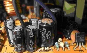
It measures the voltage across an electrolytic capacitor. He highlighted in the photo. If the voltage of 300 V - fuse is intact and all the other elements connected with it (surge protector, power cable, input) are intact.
There are models with two small capacitors. In this case, the normal functioning of these elements indicates constant pressure 150 V on each of the capacitors.
In the absence of voltage, you need to ring the diodes of the rectifier bridge, the capacitor, the fuse itself, and so on. The insidiousness of the fuses is that, having failed, they outwardly are no different from working samples. Detect a malfunction is possible only through dialing - the blown fuse will show high resistance.
Having found a faulty fuse, you should carefully inspect the board, as it often fails at the same time as other elements.
A damaged capacitor is easily noticed with the naked eye - it will be destroyed or blown up.
In this case, he does not need prozvanivanii, but simply vypivaetsya. Also the following elements are drunk and called:
- power or rectifier bridge (looks like a monolithic block or may consist of four diodes);
- a filter capacitor (looks like a large unit or several units connected in parallel or in series) located in the high-voltage part of the unit;
- transistors mounted on the radiator (these are power switches).
Important. All parts are soldered and replaced at the same time! Replacing in turn will lead to burnout of the power unit each time.
Burnt items must be replaced with new ones. The radio market offers a wide range of parts for power supplies. Finding good options at the lowest prices is pretty easy.
On a note. The fuse can be successfully replaced with a piece. copper wire . Wire thickness of 0.11 millimeter corresponds to a 3 Ampere fuse.
Causes of failure
:
- voltage drops;
- lack of protection (there is a place for it, but the element itself is not installed - so manufacturers save).
The solution to this fault switching power supplies:
- install protection (it is not always possible to find the right part);
- or use a mains voltage filter with good protective elements (not jumpers!).
What if there is no output voltage?
 Another common cause of a malfunction in the power supply has nothing to do with the fuse. We are talking about the absence of output voltage with a fully functional such an element.
Solving the problem :
- Condenser blown - watering and replacement required.
- Broken choke - you must remove the element and change the winding. The damaged wire is unwound. This is the counting of turns. Then a new wire of the suitable wire is wound on the same number of turns. The item returns to its place.
- Deformed bridge diodes are replaced with new ones.
- If necessary, the parts are checked by a tester (if no damage is visually detected).
Before that, it is imperative to learn the rules for safe use of such a tool. This device should not shine in the reflective surface, because you can damage the eyes.
Fully afford to build yourself. A fan is used as a supercharger, and a spiral is used as a heater. The best option is a circuit with a thyristor.
Causes of failure :
- poor ventilation.
Solution :
- Do not block the ventilation openings.
- ensure optimum temperature conditions - cooling and ventilation.
What you need to remember :
- The first connection of the unit is made to a lamp with a power of 25 watts. This is especially important after replacing the diodes or the transistor! If a mistake is made somewhere or a fault is not noticed, the flowing current will not damage the entire device.
- When starting work, you should not forget that a residual discharge remains for a long time on electrolytic capacitors. Before watering the parts, short the capacitor leads. Directly this can not be done. It should be short-circuited through the resistance of a nominal higher than 0.5 V.
If the entire UPS is carefully checked, but still does not work, you can contact the repair shop. Perhaps your case relates to a complex breakdown that is still amenable to correction.
According to statistics, about 5% of failures require replacing the unit. Fortunately, this device is always available. In stores you can find a rich assortment in different price categories.
Peculiarities of repairing a DVD video power supply unit
TV Bravis LED-16E96B after the voltage drop.
The power supply is assembled on the SW2658a PWM controller .
The chip is rare, but it is not strange that there is a datasheet available. And nothing more.
SW2658-type scheme. Adapter BP Chinese TV.
Power adapter, as expected died with special effects.
The TV itself was not damaged, I checked it with the help of a working power supply.
The adapter is opened with a non-sharp screwdriver and hammer. Light blows to the seam. Then a wide screwdriver razlushivaetsya further.
Visually, one of the line capacitors 15 microfarads x 400 volts swelled.
Naturally interrupted fuse. It crashed well, the board had to be washed with alcohol in some places.
At first, I didn’t even realize what the board was bloated with. Later, under a silicone, a broken L1 choke was wound on a ferrite core. Permot the same wire.
I had to throw 15 centimeters of wire. Coil was coil to coil. Motal not so neat, the first layers are smooth, then how it happened. It did not affect the performance.
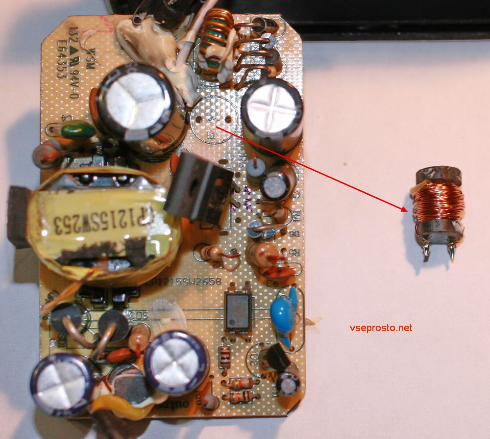
Throttle in power supply with a burnt wire
I had to remember the old technology)
I took my favorite PWM controller, which I used to put in DVD, receivers, adapters ... 5H0165R.
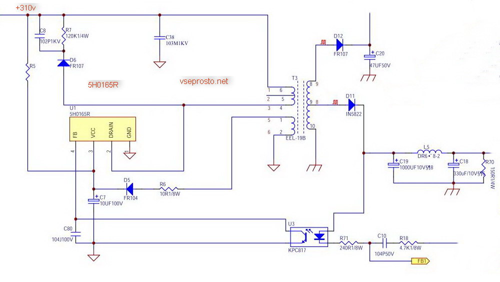
Scheme pulse unit power on the PWM controller 5H0165R
I opened two datasheets and looked at how interchangeable it was.
No need to clean up, add too. It is only necessary to form the findings as shown in the photo.
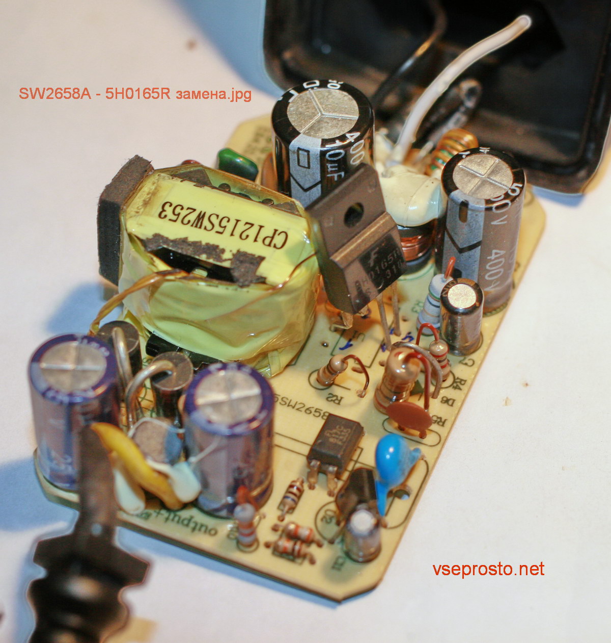
General view of the power supply, forming the findings 5H0165R instead of SW2658A
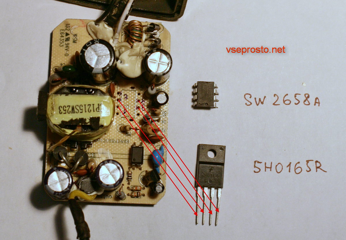
solution SW2658A - 5H0165R
The first start, as usual, through a 220-volt light bulb, 100 watts, so that nothing will beat in case of a missed fault.
SW2658A is changing to 5H0165R . Not to say that this is an analogue, but it will work even more reliably than a native microcircuit.
To improve reliability, I screwed a small radiator in the form of an aluminum plate to the 5H0165R, and I drilled 3 mm holes on the top cover of the adapter.
Network power adapters - miniature power supplies of various electronic household equipment are used to power antenna amplifiers, radio telephones, chargers . Despite the active introduction of switching power supplies, transformer power supplies are still actively used and are used in the user's home.
It is not uncommon for these transformer units to fail and break.
If the adapter breaks, you can replace it with a new one, their cost is low. But why bribe if, in most cases, you can fix the malfunction yourself within 15 to 30 minutes and save yourself from the search for replacement and spending money?
So, let's look at the composition of the usual low-power power supply and its repair
An adapter for 12V and a current of 100mA with a power of 3.6 watts from an antenna amplifier hit the repair table.
The photo of the adapter after repair.
What parts does a normal transformer adapter consist of?
If you disassemble the adapter, then inside we will find a transformer ( 1 ) and a small electronic circuit ( 2 ).
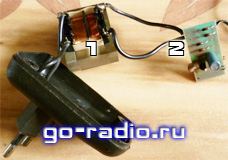
The transformer ( 1 ) is used to lower the AC mains voltage of 220V to a level of 13 - 15 V.
The electronic circuit serves for rectifying the alternating voltage (turning it into a direct voltage) and stabilizing the output voltage at 12 V.
It's simple. What can break in such a simple device?
Take a look at the schematic diagram of this adapter.
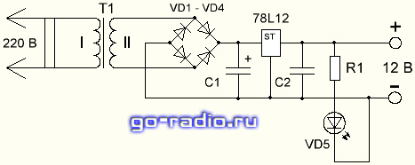
In principle, the T1 is a transformer . Typical faults Transformers are burnout or wire breakage of the primary, less often the secondary winding. As a rule, the primary, network winding ( 1 ) is faulty.
The cause of the break or burnout is a thin wire that does not withstand mains voltage spikes and overloads. Say thanks to the Chinese, they are thrifty guys, thicker the wire does not want to wind ...
Check the serviceability of the transformer is quite simple. It is necessary to measure the resistance of the primary and secondary windings. Resistance primary winding it should be several kilo ohms (1 kOhm = 1000 ohms), the secondary should be several tens ohms.
When checking the transformer adapter for the primary winding, the resistance turned out to be 1.8 kΩ, which indicates that the primary winding is operational.
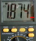
For the secondary winding, the resistance was 25.5 ohms , which is also normal.
If there is no indication, measure the resistance of the primary winding of the transformer. Make it easy, you can not even disassemble the power supply, and measure the resistance of the winding through the contacts of the power plug.
We disassemble the power supply, we make an external inspection. We draw attention to the darkened areas around the radio components, chips and cracks in the power supply stabilizer (78L12) housings, swellings of the filter capacitors.
In the process of repairing the antenna adapter, it turned out that the 78L12 stabilizer chip is faulty. The electrolytic capacitor C1 (100 microfarad 16V) was also replaced by a capacitor with a larger capacity - 470 microfarad (25V) . When replacing a capacitor, take account of the polarity of the capacitor.
Knowing the pinout (location and purpose) of the 78L12 stabilizer pins is not necessary, you must either remember, sketch or photograph the location of the faulty chip on the electronic board and solder a serviceable part as soon as you find it. This simple operation will save your time if a faulty microcircuit is dropped, and the replacement was not found in time and forgot how the microcircuit was soldered.
What if there is no output voltage?What if there is no output voltage?
But why bribe if, in most cases, you can fix the malfunction yourself within 15 to 30 minutes and save yourself from the search for replacement and spending money?
What parts does a normal transformer adapter consist of?
What can break in such a simple device?
